Monday 23 January 2017

BASIC Tech Group - MyNews 20 - Some useful Hellschreiber font sketches

When writing some sketches for Hellscreiber transmission, you need bit mapped fonts.

A font is made up of glyphs (or characters), each glyph is made up of columns and rows of pixels.

Glyphs come as bit maps, sizes 5x7 and 3x5, that is 5 cols x 7 rows, or the very small 3 cols x 5 rows. They are stored in an array, part of which is shown below. The first column is the glyph in ASCII that can be scanned to find the following bit map. for example, 3x5:

Screen Shot 2017 01 23 at 11 26 15

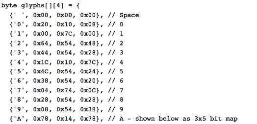
Data is stored in an array of bytes for each column. e.g. 5 columns of 7 rows. For example:

Screen Shot 2017 01 23 at 11 26 58

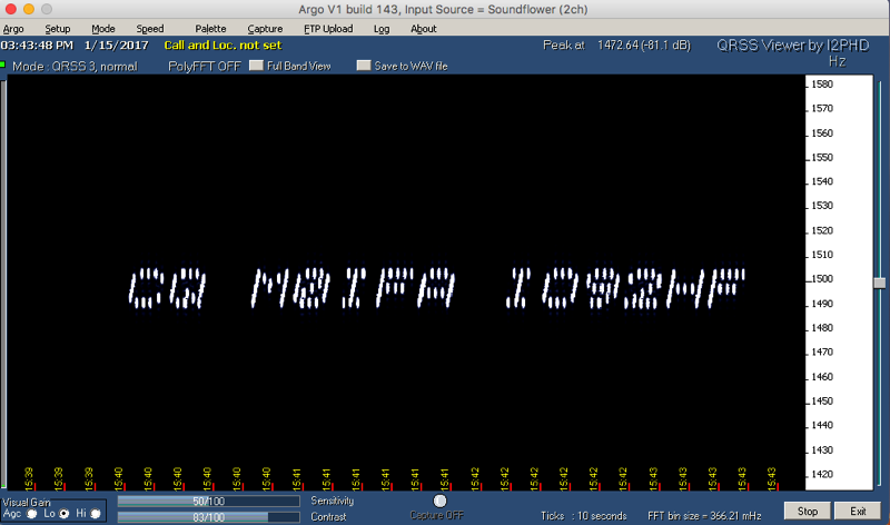
When transmitted the columns are scanned in the direction of bottom to top and the output frequency is shifted from the BASEFREQ, upwards in steps of SHIFT. a pixel is transmitted if the map contains a ‘1’. The pixels are transmitted for a PIXTIME of 200-500ms, scanning only the area defining the glyph, from bottom to top: so b1-b7 for 5x7 or b1-b5 for 3x5.

Below are a couple of fonts in Arduino IDE ".ino" files that were found in the internet, take care... these are up-side-down as normal graphic representation start the bit map at top left, and go down not up. Here also is a simple program for inverting these fonts, output is to the Monitor screen from where they can be cut and pasted into other sketches.

Code

void setup() {
  // put your setup code here, to run once:

}

void loop() {
  // put your main code here, to run repeatedly:

}

// font3x5 +1 array
byte glyphs[]4] = {
  {' ', 0x00, 0x00, 0x00}, // Space
  {'0', 0x20, 0x10, 0x08}, // 0
  {'1', 0x00, 0x7C, 0x00}, // 1
  {'2', 0x64, 0x54, 0x48}, // 2
  {'3', 0x44, 0x54, 0x28}, // 3
  {'4', 0x1C, 0x10, 0x7C}, // 4
  {'5', 0x4C, 0x54, 0x24}, // 5
  {'6', 0x38, 0x54, 0x20}, // 6
  {'7', 0x04, 0x74, 0x0C}, // 7
  {'8', 0x28, 0x54, 0x28}, // 8
  {'9', 0x08, 0x54, 0x38}, // 9
  {'A', 0x78, 0x14, 0x78}, // A
  {'B', 0x7C, 0x54, 0x28}, // B
  {'C', 0x38, 0x44, 0x44}, // C
  {'D', 0x7C, 0x44, 0x38}, // D
  {'E', 0x7C, 0x54, 0x44}, // E
  {'F', 0x7C, 0x14, 0x04}, // F
  {'G', 0x38, 0x44, 0x34}, // G
  {'H', 0x7C, 0x10, 0x7C}, // H
  {'I', 0x00, 0x7C, 0x00}, // I
  {'J', 0x20, 0x40, 0x3C}, // J
  {'K', 0x7C, 0x10, 0x6C}, // K
  {'L', 0x7C, 0x40, 0x40}, // L
  {'M', 0x7C, 0x08, 0x7C}, // M
  {'N', 0x7C, 0x04, 0x7C}, // N
  {'O', 0x7C, 0x44, 0x7C}, // O
  {'P', 0x7C, 0x14, 0x08}, // P
  {'Q', 0x38, 0x44, 0x78}, // Q
  {'R', 0x7C, 0x14, 0x68}, // R
  {'S', 0x48, 0x54, 0x24}, // S
  {'T', 0x04, 0x7C, 0x04}, // T
  {'U', 0x7C, 0x40, 0x7C}, // U
  {'V', 0x3C, 0x40, 0x3C}, // V
  {'W', 0x7C, 0x20, 0x7C}, // W
  {'X', 0x6C, 0x10, 0x6C}, // X
  {'Y', 0x1C, 0x60, 0x1C}, // Y
  {'Z', 0x64, 0x54, 0x4C}  // Z
};
3x5 vfont


void setup() {
  // put your setup code here, to run once:

}

void loop() {
  // put your main code here, to run repeatedly:

}
// font 5x7
// table of glyphs 0-9 & A-Z
byte glyphs[][6] = {
  {' ', 0x00, 0x00, 0x00, 0x00, 0x00}, // 20 SP
  {'/', 0x20, 0x10, 0x08, 0x04, 0x02}, // 2F /
  {'0', 0x3e, 0x51, 0x49, 0x45, 0x3e}, // 30 0
  {'1', 0x00, 0x42, 0x7f, 0x40, 0x00}, // 31 1
  {'2', 0x42, 0x61, 0x51, 0x49, 0x46}, // 32 2
  {'3', 0x21, 0x41, 0x45, 0x4b, 0x31}, // 33 3
  {'4', 0x18, 0x14, 0x12, 0x7f, 0x10}, // 34 4
  {'5', 0x27, 0x45, 0x45, 0x45, 0x39}, // 35 5
  {'6', 0x3c, 0x4a, 0x49, 0x49, 0x30}, // 36 6
  {'7', 0x01, 0x71, 0x09, 0x05, 0x03}, // 37 7
  {'8', 0x36, 0x49, 0x49, 0x49, 0x36}, // 38 8
  {'9', 0x06, 0x49, 0x49, 0x29, 0x1e}, // 39 9
  {'A', 0x7e, 0x11, 0x11, 0x11, 0x7e}, // 41 A
  {'B', 0x7f, 0x49, 0x49, 0x49, 0x36}, // 42 B
  {'C', 0x3e, 0x41, 0x41, 0x41, 0x22}, // 43 C
  {'D', 0x7f, 0x41, 0x41, 0x22, 0x1c}, // 44 D
  {'E', 0x7f, 0x49, 0x49, 0x49, 0x41}, // 45 E
  {'F', 0x7f, 0x09, 0x09, 0x09, 0x01}, // 46 F
  {'G', 0x3e, 0x41, 0x49, 0x49, 0x7a}, // 47 G
  {'H', 0x7f, 0x08, 0x08, 0x08, 0x7f}, // 48 H
  {'I', 0x00, 0x41, 0x7f, 0x41, 0x00}, // 49 I
  {'J', 0x20, 0x40, 0x41, 0x3f, 0x01}, // 4a J
  {'K', 0x7f, 0x08, 0x14, 0x22, 0x41}, // 4b K
  {'L', 0x7f, 0x40, 0x40, 0x40, 0x40}, // 4c L
  {'M', 0x7f, 0x02, 0x0c, 0x02, 0x7f}, // 4d M
  {'N', 0x7f, 0x04, 0x08, 0x10, 0x7f}, // 4e N
  {'O', 0x3e, 0x41, 0x41, 0x41, 0x3e}, // 4f O
  {'P', 0x7f, 0x09, 0x09, 0x09, 0x06}, // 50 P
  {'Q', 0x3e, 0x41, 0x51, 0x21, 0x5e}, // 51 Q
  {'R', 0x7f, 0x09, 0x19, 0x29, 0x46}, // 52 R
  {'S', 0x46, 0x49, 0x49, 0x49, 0x31}, // 53 S
  {'T', 0x01, 0x01, 0x7f, 0x01, 0x01}, // 54 T
  {'U', 0x3f, 0x40, 0x40, 0x40, 0x3f}, // 55 U
  {'V', 0x1f, 0x20, 0x40, 0x20, 0x1f}, // 56 V
  {'W', 0x3f, 0x40, 0x38, 0x40, 0x3f}, // 57 W
  {'X', 0x63, 0x14, 0x08, 0x14, 0x63}, // 58 X
  {'Y', 0x07, 0x08, 0x70, 0x08, 0x07}, // 59 Y
  {'Z', 0x61, 0x51, 0x49, 0x45, 0x43}, // 5a Z
};
// Font_Reverse
// writes the font up-side-down to the monitor,
// open this first then upload sketch
// monitor output can then be copied into the glyphs array in other programs
// it allows pixel columns to be output bottom up pix = 0 to 7

// paste the source font here
byte glyphs[][4] = {
  {' ', 0x00, 0x00, 0x00}, // Space
  {'0', 0x20, 0x10, 0x08}, // 0
  {'1', 0x00, 0x7C, 0x00}, // 1
  {'2', 0x64, 0x54, 0x48}, // 2
  {'3', 0x44, 0x54, 0x28}, // 3
  {'4', 0x1C, 0x10, 0x7C}, // 4
  {'5', 0x4C, 0x54, 0x24}, // 5
  {'6', 0x38, 0x54, 0x20}, // 6
  {'7', 0x04, 0x74, 0x0C}, // 7
  {'8', 0x28, 0x54, 0x28}, // 8
  {'9', 0x08, 0x54, 0x38}, // 9
  {'A', 0x78, 0x14, 0x78}, // A
  {'B', 0x7C, 0x54, 0x28}, // B
  {'C', 0x38, 0x44, 0x44}, // C
  {'D', 0x7C, 0x44, 0x38}, // D
  {'E', 0x7C, 0x54, 0x44}, // E
  {'F', 0x7C, 0x14, 0x04}, // F
  {'G', 0x38, 0x44, 0x34}, // G
  {'H', 0x7C, 0x10, 0x7C}, // H
  {'I', 0x00, 0x7C, 0x00}, // I
  {'J', 0x20, 0x40, 0x3C}, // J
  {'K', 0x7C, 0x10, 0x6C}, // K
  {'L', 0x7C, 0x40, 0x40}, // L
  {'M', 0x7C, 0x08, 0x7C}, // M
  {'N', 0x7C, 0x04, 0x7C}, // N
  {'O', 0x7C, 0x44, 0x7C}, // O
  {'P', 0x7C, 0x14, 0x08}, // P
  {'Q', 0x38, 0x44, 0x78}, // Q
  {'R', 0x7C, 0x14, 0x68}, // R
  {'S', 0x48, 0x54, 0x24}, // S
  {'T', 0x04, 0x7C, 0x04}, // T
  {'U', 0x7C, 0x40, 0x7C}, // U
  {'V', 0x3C, 0x40, 0x3C}, // V
  {'W', 0x7C, 0x20, 0x7C}, // W
  {'X', 0x6C, 0x10, 0x6C}, // X
  {'Y', 0x1C, 0x60, 0x1C}, // Y
  {'Z', 0x64, 0x54, 0x4C}  // Z
};
byte revglyphs[40][6];

void setup() {
  int r, c;  // row and col

  Serial.begin(9600);

  Serial.println("Font reverse");

  for (r = 0; r < ((sizeof glyphs) / (sizeof glyphs[0])); r++) {
    Serial.print("{'");
    Serial.write(glyphs[r][0]);
    Serial.print("', ");
    for (c = 1; c < 4; c++) {
      revglyphs[r][c] =  reverse(glyphs[r][c]);
      Serial.print("0x");
      if(revglyphs[r][c] < 0x0f) Serial.print("0");
      Serial.print(revglyphs[r][c], HEX);
      Serial.print(", ");
    }
    Serial.println("},");
  }
}

void loop() {
  // put your main code here, to run repeatedly:

}

byte reverse(byte b) {
   b = (b & 0xF0) >> 4 | (b & 0x0F) << 4;
   b = (b & 0xCC) >> 2 | (b & 0x33) << 2;
   b = (b & 0xAA) >> 1 | (b & 0x55) << 1;
   return b;
}

Thursday 12 January 2017

BASIC Tech Group - MyNews 19 - Simple VFO varicap tuned

I recently did the course for the Intermediate Amateur Radio exam. Part of this course is to build a small piece of electronics, another part of the course is to calibrate a VFO. This teaches the understanding of not transmitting outside the Band edges.

I grabbed the opportunity to build a simple VFO, and because I am deep into Arduino designs I decided to design a varicap tuned VFO for 40m constructed on an Arduino Shield. Here's the schematic and PCB layout.

Screen Shot 2017 01 12 at 17 39 28

Screen Shot 2017 01 12 at 17 39 41

This is the finished board

IMG 0535

Showing the output on a frequency meter, at around 6.9MHz. The tuning range, without adjusting the coil, is 6.9-7,5MHz.

Wednesday 11 January 2017

BASIC Tech Group - MyNews 18 - HELL_S/MT_5x7

One of the interesting things to do when operating narrow band is to use the QRSS frequencies which normally transmit slow morse or DFCW (dual frequency CW), to instead transmit ASCII characters on a set of 8 bit mapped frequencies, this sends a bit mapped font character.

This results in a display at QRSS3 speeds as shown in Argo software:

Screen Shot 2017 01 11 at 16 16 13

I am using an SDR receiver (this one is the Elektor SDR) tuned to 7050kHz centre frequency, with the IQ outputs going to a Startech A/D and on to my iMac computer. I am running the HDSDR software (under Wine) tuned to 7038.7kHz USB, so giving an audio tone of 1500kHz displayed in Argo

IMG 0539

The transmitter is an Arduino UNO programming an Si5351 synthesiser module. This includes an RTC and TX is made every 5 mins

IMG 0538

And here's couple more photos using the SDR_40M "Concept" SDR and Mac native DSP Radio software, audio is sent from the Radio to Argo using Soundflower software (recently updated for MacOS 10 and much improved)

Screen Shot 2017 01 15 at 15 37 48

Updated message after I got my Full Licence...

Screen Shot 2017 01 15 at 15 43 40

The code below is for transmission of an embedded line "CQ M0IFA IO92HF" (replace this with your text, max 16 characters if you want it to display on the LCD screen). The font here is a normal right-way-up font.

Code - updated 5-2-17

// HELL_S/MT_5x7 Sequential MultiTone Hellschreiber
// 5x7 font, normal
// Si5351 correction for ARDUINO COURSE BB, may need adustment
// Si5351 I2C bus
// SDA = A4
// SCL = A5
// LCD I2C bus (16x2)
// SDA = A4
// SCL = A5
// rotary encoder pins
// DT = 2
// CLK = 3
// SW = 4

// Si5351, LCDI2C libraries
#include "si5351.h"
#include "LiquidCrystal_I2C.h"

// LCD 0x27 or 0x3F
//#define LCDADDR 0x3F
#define LCDADDR 0x27
#define LCDCOLS 16
#define LCDROWS 2

// frequencies, base and shift (cHz)
#define BASEFREQ 707000000  // 40m, freqs 7077, 10132, 14070kHz
#define SHIFT 200           // 2Hz shift, 14Hz total BW

//each pixel 300ms, chargap 5pix = 1500ms
#define PIXTIME 300
#define CHARGAP 1500

// table of glyphs 0-9 & A-Z, cols b0-b7
byte glyphs[][6] = {
  {' ', 0x00, 0x00, 0x00, 0x00, 0x00, },
  {'/', 0x04, 0x08, 0x10, 0x20, 0x40, },
  {'0', 0x7C, 0x8A, 0x92, 0xA2, 0x7C, },
  {'1', 0x00, 0x42, 0xFE, 0x02, 0x00, },
  {'2', 0x42, 0x86, 0x8A, 0x92, 0x62, },
  {'3', 0x84, 0x82, 0xA2, 0xD2, 0x8C, },
  {'4', 0x18, 0x28, 0x48, 0xFE, 0x08, },
  {'5', 0xE4, 0xA2, 0xA2, 0xA2, 0x9C, },
  {'6', 0x3C, 0x52, 0x92, 0x92, 0x0C, },
  {'7', 0x80, 0x8E, 0x90, 0xA0, 0xC0, },
  {'8', 0x6C, 0x92, 0x92, 0x92, 0x6C, },
  {'9', 0x60, 0x92, 0x92, 0x94, 0x78, },
  {'A', 0x7E, 0x88, 0x88, 0x88, 0x7E, },
  {'B', 0xFE, 0x92, 0x92, 0x92, 0x6C, },
  {'C', 0x7C, 0x82, 0x82, 0x82, 0x44, },
  {'D', 0xFE, 0x82, 0x82, 0x44, 0x38, },
  {'E', 0xFE, 0x92, 0x92, 0x92, 0x82, },
  {'F', 0xFE, 0x90, 0x90, 0x90, 0x80, },
  {'G', 0x7C, 0x82, 0x92, 0x92, 0x5E, },
  {'H', 0xFE, 0x10, 0x10, 0x10, 0xFE, },
  {'I', 0x00, 0x82, 0xFE, 0x82, 0x00, },
  {'J', 0x04, 0x02, 0x82, 0xFC, 0x80, },
  {'K', 0xFE, 0x10, 0x28, 0x44, 0x82, },
  {'L', 0xFE, 0x02, 0x02, 0x02, 0x02, },
  {'M', 0xFE, 0x40, 0x30, 0x40, 0xFE, },
  {'N', 0xFE, 0x20, 0x10, 0x08, 0xFE, },
  {'O', 0x7C, 0x82, 0x82, 0x82, 0x7C, },
  {'P', 0xFE, 0x90, 0x90, 0x90, 0x60, },
  {'Q', 0x7C, 0x82, 0x8A, 0x84, 0x7A, },
  {'R', 0xFE, 0x90, 0x98, 0x94, 0x62, },
  {'S', 0x62, 0x92, 0x92, 0x92, 0x8C, },
  {'T', 0x80, 0x80, 0xFE, 0x80, 0x80, },
  {'U', 0xFC, 0x02, 0x02, 0x02, 0xFC, },
  {'V', 0xF8, 0x04, 0x02, 0x04, 0xF8, },
  {'W', 0xFC, 0x02, 0x1C, 0x02, 0xFC, },
  {'X', 0xC6, 0x28, 0x10, 0x28, 0xC6, },
  {'Y', 0xE0, 0x10, 0x0E, 0x10, 0xE0, },
  {'Z', 0x86, 0x8A, 0x92, 0xA2, 0xC2, },
};

// calc number of glyphs in glyphs table
#define NGLYPHS ((sizeof glyphs) / (sizeof glyphs[0]))

// freq variable
uint64_t freq = BASEFREQ; // base or bottom freq of pixels

// message to send
char msg[] = "TESTING M0IFA"; // max 16 char for LCD display, can transmit longer

// dds object
Si5351 dds;

// LCD object
LiquidCrystal_I2C lcd(LCDADDR, LCDCOLS, LCDROWS);

void setup() {
  // init lcd & I2C
  lcd.begin();

  // init dds
  dds.init(SI5351_CRYSTAL_LOAD_8PF, 0, 0);

  // set drive output 8mA (about 4dBm into 50R)
  dds.drive_strength(SI5351_CLK0, SI5351_DRIVE_8MA);

  // disable all outputs
  dds.output_enable(SI5351_CLK0, 0);
  dds.output_enable(SI5351_CLK1, 0);
  dds.output_enable(SI5351_CLK2, 0);

  // initial display
  dispMsg(0, 0, " HELLSCHREIBER    ");        // title & clear line
  Serial.println("START 1 sec");
  delay(1000);
}

void loop() {
  dispMsg(0, 0, "                 ");        // clear title
  dispMsg(0, 0, msg);                        // disp msg
  dispFreq(1, 1, freq, 1);                   // display freq
  dispMsg(11, 1, " USB ");

  sendMsg(msg);

  dispMsg(11, 1, "     ");
  dispMsg(0, 0, " HELLSCHREIBER    ");        // title & clear line
  dispMsg(0, 1, "                  ");

  delay(30000);                              // next 30sec delay
}

// take glyphs of message and send
void sendMsg(char *m) {
  int c, i, j;                                               // c scans msg, i & j scan the glyphs & rows
  int pix;                                                   // pix scans pixel cols in glyph

  c = 0;
  while (m[c] != '\0') {                                     // scan until end of msg
    for (i = 0; i < NGLYPHS; i++) {                          // scan glyphs, always scan all rows to preserve timing
      if (m[c] == glyphs[i][0]) {                            // if m[c] found at [i][0]
        for (j = 1; j <= 5; j++) {                           // read glyphs[j][1] to [j][5]
          for (pix = 1; pix <= 7; pix++) {                   // font cols b1-b7 for USB
            if (bitRead(glyphs[i][j], pix) == 1) {           // send pix
              outFreq(freq + (pix * SHIFT), PIXTIME);        // calc output freq
            }
            else {
              delay(PIXTIME);
            }
          }
        }
        delay(CHARGAP);
      }
    }
    c++;
  }
}

// output f for t ms
void outFreq(uint64_t f, uint16_t t) {
  dds.set_freq(f, SI5351_CLK0);                   // output freq
  dds.output_enable(SI5351_CLK0, 1);
  delay(t);
  dds.output_enable(SI5351_CLK0, 0);
}

// display freq in kHz,col c, row r, d decimal places
void dispFreq(uint8_t c, uint8_t r, uint64_t f, uint8_t d)
{
  lcd.setCursor(c, r); // clear last freq display
  lcd.print((float)f / 100000, d); // convert to float for print function
  lcd.print("kHz  "); // + trailing spaces to clear previous display
}

// display a number at col c, row r
void dispNum(uint8_t c, uint8_t r, uint16_t n)
{
  lcd.setCursor(c, r);
  lcd.print(n);
}

// display char msg at col c, row r
void dispMsg(uint8_t c, uint8_t r, char *m)
{
  lcd.setCursor(c, r);
  lcd.print(m);
}


Friday 6 January 2017

BASIC Tech Group - MyNews 17 - The Arduino Zoo

I have always up to now used the plain ordinary Arduino UNO. But there's growing, burgeoning explosion of "clones" on the market, from Chinese eBay and more steady suppliers like Sparkfun.

These "clones" and even new development versions from Arduino themselves present considerable problems to users. The biggest issues seem to be

- Diffferent USB connectors, micro, mini and standard

- Different USB interface chips, or USB implemented in software.

- Different supply and I/O voltages 3.3/5V

My original search was fro a plain old Arduino UNO R3, but fitted with a small USB connector, either the micro or the mini. But I have not found anything - seems strange as this would seem to me to be one of the most useful modifications... giving a lower profile to the board and better spacing to shields plugged directly on top (especially my own shields that use this space above the USB connector for a new 8 pin header carrying RF signals.

So the ZOO:

IMG 8181

The original Arduino UNO: Standard FTDI USB interface chip and large USB connector. (The tape stuck on the connector is to prevent short-circuits from the RF header which will plug in above!)

IMG 5761

A fancy version of the UNO,:with built-in WiFi. This is a development board which Arduino sent me free but which I have not done anything with yet. Trying to think how to make a remote controlled SDR TXRX with this board, but I will need help with the software.

IMG 5277

The one I thought I wanted: an UNO with a mini USB connector, but those screwy Chinese did not use the industry standards FTDI USB interface chip - they don't make it and can't copy it... So they used a CH340 chip. Normally a Mac will automatically load a driver for any USB device plugged in, for this chip it does NOT. There is about on the web a "driver" but I am highly suspicious of Chinese drivers, and all the documentation is in Chinese!

IMG 0732

Finally one from SparkFun, called the "Lite". This has a micro USB socket, and software implemented USB as far as I can tell. It identifies itself as an Arduino Leonardo to the Mac and the IDE. But I have been unable to upload my sketches to it. It accepts the Arduino Example Basic01 Blink sketch. But not mine. I guess some of the libraries I use are incompatible?

Tiresome!

Thursday 5 January 2017

BASIC Tech Group - MyNews 16 - WSPR code for 30m

Here's the code for 30m WSPR transmissions, it has my new call sign embedded. Reminder: the code runs on my Arduino shield using a Si5351 modules and a DS3231 RTC module for timing. The time has to be set to the nearest 1sec using special sketch.

IMG 5260

Code

// WSPR_30M-Basic
// Uses WsprMessage library of John Newcombe
// reads time from RTC, must be set accurately by spearate program
// Si5351 I2C bus
// SDA = A4
// SCL = A5
// LCD I2C bus (16x2)
// SDA = A4
// SCL = A5
// rotary encoder pins
// DT = 2
// CLK = 3
// SW = 4

#include "WsprMessage.h"
#include "si5351.h"
#include "LiquidCrystal_I2C.h"

// LCD 0x27 or 0x3F
#define LCDADDR 0x27
//#define LCDADDR 0x3F
#define LCDCOLS 16
#define LCDROWS 2

// RTC address
#define RTCADDR 0x68

// RTC time
byte sec, mns, hrs;

// repeat TX interval (sec)
uint8_t repeat;

// WSPR data
char callsign[] = " M0IFA";            // your callsign
char loc_short[] = "IO92";            // your short locator
int power = 20;                       // transmit power in dBm
char msgtxt[] = {" M0IFA IO92 20  "}; // msg displayed on lcd

// WSPR Frequency
uint64_t WSPRFreq = 1014020000;       // WSPR frequency (cHz)

// WSPR Delta Freq for symbols 0, 1, 2, 3. = 145.48 x 0, 1, 2 and 3 to nearest cHz
uint64_t delta[] = {0, 145, 291, 436};

// Data from WsprMessage
unsigned char *sym;                   // ptr to symbol vector from WsprMessage

// blank MSG_ZISE (= 162) char array for WSPR message, will be populated (0, 1, 2 or 3) in setup() by WsprMessage
char WSPR_Message[] = {
0, 0, 0, 0, 0, 0, 0, 0, 0, 0, 0, 0, 0, 0, 0, 0, 0, 0, 0, 0, 0, 0, 0, 0, 0, 0, 0, 0, 0, 0,
0, 0, 0, 0, 0, 0, 0, 0, 0, 0, 0, 0, 0, 0, 0, 0, 0, 0, 0, 0, 0, 0, 0, 0, 0, 0, 0, 0, 0, 0,
0, 0, 0, 0, 0, 0, 0, 0, 0, 0, 0, 0, 0, 0, 0, 0, 0, 0, 0, 0, 0, 0, 0, 0, 0, 0, 0, 0, 0, 0,
0, 0, 0, 0, 0, 0, 0, 0, 0, 0, 0, 0, 0, 0, 0, 0, 0, 0, 0, 0, 0, 0, 0, 0, 0, 0, 0, 0, 0, 0,
0, 0, 0, 0, 0, 0, 0, 0, 0, 0, 0, 0, 0, 0, 0, 0, 0, 0, 0, 0, 0, 0, 0, 0, 0, 0, 0, 0, 0, 0,
0, 0, 0, 0, 0, 0, 0, 0, 0, 0, 0, 0};

// create SI5351 object
Si5351 dds;

// create LCD object
LiquidCrystal_I2C lcd(LCDADDR, LCDCOLS, LCDROWS);

//=======SETUP========
void setup() {
  // init I2C
  Wire.begin();

  // init lcd
  lcd.begin();
  lcd.backlight();
  
  // init dds
  dds.init(SI5351_CRYSTAL_LOAD_8PF, 0, 0);

  // set 8mA output drive (max possible)
  dds.drive_strength(SI5351_CLK0, SI5351_DRIVE_8MA);
  
  // init transmit frequency, set freq 1st as turns outputs on
  dds.set_freq(WSPRFreq, SI5351_CLK0);
  
  // disable outputs (CLK0 enabled on TX)
  dds.output_enable(SI5351_CLK0, 0);
  dds.output_enable(SI5351_CLK1, 0);
  dds.output_enable(SI5351_CLK2, 0);

  // build WSPR message, get size and pointer to symbols
  WsprMessage WsprMessage(callsign, loc_short, power);
  sym = WsprMessage.symbols;            // get address ptr to symbols
  for(int i = 0; i < 162; i++) {        // copy sym array to WSPR_Message array
    WSPR_Message[i] = sym[i];           // both are char arrays, same as bytes
  }

  repeat = 2;                           // defalt repeat WSPR TX every 2 minutes

  // initial display
  dispMsg(0, 0, "WSPR            ");
  dispFreq(5, 0, WSPRFreq, 2); // display freq b
  dispNum(0, 1, repeat);
  dispMsg(1, 1, " min   ");
}

// ========MAIN LOOP=========
void loop() {
  // get time & display
  getRTC();
  dispTime(8, 1);

  // send WSPR?
  if (mns % repeat == 0 && sec == 0)
  {
    // display message
    dispMsg(0, 0, msgtxt);
    dispMsg(8, 1, "     TX ");              // show transmit
 
    sendWspr(682);                          // transmit on freq. 682ms per suymbol 162 * 682 = 110.48 sec total frame

    // restore display
    dispMsg(0, 0, "WSPR           ");
    dispFreq(5, 0, WSPRFreq, 2); // display freq
    dispMsg(1, 1, " min           ");
    dispNum(0, 1, repeat);
  }
}

//========WSPR send routine
void sendWspr(int SymbolLength) {
  // Send WSPR Message
  dds.output_enable(SI5351_CLK0, 1);                                      // enable CLK0 output
  for  (int s = 0; s < MSG_SIZE; s++) {                                   // For all symbols, MSG_SIZE in WsprMessage.h
    dds.set_freq(WSPRFreq + delta[WSPR_Message[s]], SI5351_CLK0);         // transmit frequency
    delay(SymbolLength);                                                  // symbol timing
  }
  dds.output_enable(SI5351_CLK0, 0);                                      // disable CLK0 output
}

// get time from RTC, convert bcd to decimal
void getRTC()
{
  // Reset the register pointer
  Wire.beginTransmission(RTCADDR);
  byte zero = 0x00;
  Wire.write(zero);
  Wire.endTransmission();

  // request 1st 3 bytes from the RTC address
  Wire.requestFrom(RTCADDR, 3);

  // get the s/m/h time data
  sec = bcdToDec(Wire.read());
  mns = bcdToDec(Wire.read());
  hrs = bcdToDec(Wire.read() & 0b111111); // mask 24 hour time bit
}

// Convert binary coded decimal to normal decimal numbers
byte bcdToDec(byte val)
{
  return ( (val / 16 * 10) + (val % 16) );
}

//=======Display routines
// display freq in kHz,col c, row r, d decimal places
void dispFreq(uint8_t c, uint8_t r, uint64_t f, uint8_t d)
{
  lcd.setCursor(c, r); // clear last freq display
  lcd.print((float)f / 100000, d); // convert to float for print function
  lcd.print("kHz  "); // + trailing spaces to clear previous display
}

// display char msg at col c, row r
void dispMsg(uint8_t c, uint8_t r, char *m)
{
  lcd.setCursor(c, r);
  lcd.print(m);
}

// display a number at col c, row r
void dispNum(uint8_t c, uint8_t r, uint16_t n)
{
  lcd.setCursor(c, r);
  lcd.print(n);
}

// display time at col, row
void dispTime(byte c, byte r) {
  lcd.setCursor(c, r);
  if (hrs < 10)
    lcd.print("0");
  lcd.print(hrs);
  lcd.print(":");
  if (mns < 10)
    lcd.print("0");
  lcd.print(mns);
  lcd.print(":");
  if (sec < 10)
    lcd.print("0");
  lcd.print(sec);
}

Tuesday 3 January 2017

BASIC Tech Group - MyNews 15 - Elektor Arduino SDR

I rushed an order out for the new Elektor SDR as soon as I discovered it on the Web. It arrived this morning.

Note: If you read this blog before, revised VFO code V3 is listed below, now covers 2-30MHz and includes frequency corrections

IMG 7170

I have already designed and built an SDR for use with the Arduino (see github.com/M6KWH). This SDR had a custom sketch written for Ham use on 40m.

The system uses a rotary encoder KY-40 and an LCD 1602 to tune and display the frequency.

IMG 9259

IMG 1759

I am using HDSDR software running under Wine on a Macbook and this works fine.

Comments on the design:

The antenna connection would be better if it was laid out for an SMA connector. And a actual 50R input matching would be better. Connections could be added on the right side for a rotary encoder (5pins) and an LCD display (4 pins). Instead of the usual peak in the centre of the SDR display, usually caused by 50Hz mains hum, there is a dip! Clever design or a mistake, I don't know.

Now how about a complementary Transmitter board Elektor?

According to me the frequency is not correct, it is about 1.4kHz wrong, maybe the xtal is not exactly on 25MHz? Looking at the xtal spec it says 18pF load, the max of the Si5351 is 8pF... So a software error correction, a large one, has to be used. This is in the code below I have calibrated against one of the Si5351 modules from Adafruit or Kanga which I have found to be very accurate.

Code

// SDR_ELEKTOR
// V3 3-3-17
// Output 4 x 2-30MHz on CLK1, in 10kHz-1MHz steps
// Si5351 I2C bus
// SDA = A4
// SCL = A5
// LCD I2C bus (16x2)
// SDA = A4
// SCL = A5
// rotary encoder pins
// DT = 2
// CLK = 3
// SW = 4

// Si5351 V2, LCD and Rotary Encoder libraries
#include "si5351.h"
#include "LiquidCrystal_I2C.h"
#include "Rotary.h"

// chose address of 0x27 or 0x3F for LCD
#define LCDADDR 0x27
//#define LCDADDR 0x3F
#define LCDCOLS 16
#define LCDROWS 2

// chose pin 2,3 or 3,2 for encoder
#define DT 2
//#define DT 3
#define CLK 3
//#define CLK 2
#define SW 4

// xtal correction for Elektor DDS
#define CORRE 180000

// min freq 7.0MHz, max 7.2MHz (cHz)
#define FREQMIN 700000000
#define FREQMAX 720000000

// freq steps 100kHz max, 10kHz step (cHz)
#define FREQSTEPMAX 10000000
#define FREQSTEP 1000000

// dds object
Si5351 dds;

// lcd object
LiquidCrystal_I2C lcd(LCDADDR, LCDCOLS, LCDROWS);

// Encoder object
Rotary enc = Rotary(DT, CLK);

// start freq & freqStep (cHz)
volatile uint64_t freq = 710000000; // 7.1MHz
volatile uint64_t freqStep = 1000000; // 10kHz

// freq change flag
volatile bool freqChange;

void setup() {
  // encoder, button pins
  pinMode(DT, INPUT_PULLUP);
  pinMode(CLK, INPUT_PULLUP);
  pinMode(SW, INPUT_PULLUP);

  // setup interrupts from DT or CLK for tuning
  attachInterrupt(digitalPinToInterrupt(DT), freqTune, CHANGE);
  attachInterrupt(digitalPinToInterrupt(CLK), freqTune, CHANGE);

  // enable interrupts
  interrupts();

  // init LCD
  lcd.begin();

  // init dds si5351 module, "0" = default 25MHz XTAL, correction
  dds.init(SI5351_CRYSTAL_LOAD_8PF, 0, CORRE);

  // set 8mA output drive
  dds.drive_strength(SI5351_CLK1, SI5351_DRIVE_8MA);

  // enable VFO output CLK1, disable CLK0 & 2
  dds.output_enable(SI5351_CLK0, 0);
  dds.output_enable(SI5351_CLK1, 1);
  dds.output_enable(SI5351_CLK2, 0);

  freqOut(freq); // cHz, output freq
  freqChange = false;

  dispMsg(2, 0, "SDR ELEKTOR");
  dispFreq(0, 1, freq, 0); // display freq
  dispfreqStep(10, 1, freqStep); // display freqStep xxxxHz|kHz col 10, row 1
}

void loop() {
  // freqStep?
  if (button()) {
    dispfreqStep(10, 1, freqStep); // display freq step
  }
  if (freqChange) {
    freqOut(freq);
    freqChange = false;
    dispFreq(0, 1, freq, 1); // display freq
  }
}

// ISR - encoder interrupt service routine
void freqTune() {
  unsigned char result;
  
  result = enc.process();
  if (result == DIR_CW && freq < FREQMAX) {
    freq += freqStep;
    freqChange = true;
  }
  else if (result == DIR_CCW && freq > FREQMIN) {
    freq -= freqStep;
    freqChange = true;
  }
}

// change freqStep, 10kHz to 1MHz
bool button() {
  if (digitalRead(SW) == LOW) { // button pressed?
    while (!digitalRead(SW)); // wait for release
    if (freqStep == FREQSTEPMAX) freqStep = FREQSTEP; // back to 10kHz
    else freqStep = freqStep * 10; // or increase by x10
    return true;
  }
  else {
    return false;
  }
}

// Output Freq for Elektor SDR, f (cHz) x 4 on CLK1
void freqOut(uint64_t f) {
  dds.set_freq(f * 4ULL, SI5351_CLK1);
}

// display freq at c)ol, r)ow, f (cHz), to d decimal places (kHz)
void dispFreq(uint8_t c, uint8_t r, uint64_t f, uint8_t d) {
  lcd.setCursor(c, r);
  lcd.print((float)f / 100000, d); // convert to float & kHz
  lcd.print("kHz ");
}

// display at c)ol, r)ow freq step s (cHz)
void dispfreqStep(byte c, byte r, uint64_t s)
{
  lcd.setCursor(c, r);
  switch (s) // display freqStep
  {
    case 1000:
      lcd.print("10Hz     ");
      break;
    case 10000:
      lcd.print("100Hz    ");
      break;
    case 100000:
      lcd.print("1kHz     ");
      break;
    case 1000000:
      lcd.print("10kHz    ");
      break;
    case 10000000:
      lcd.print("100kHz   ");
      break;
    case 100000000:
      lcd.print("1MHz     ");
      break;
  }
}

// display msg *m at c)ol, r)ow
void dispMsg(uint8_t c, uint8_t r, char *m)
{
  lcd.setCursor(c, r);
  lcd.print(m);
}

BASIC Tech Group - MyNews 14 - RETURN_LOSS-Basic

A Return Loss Bridge

Here are the details of the prototype of my Return Loss Bridge. It has been built on an Arduino breadboard with manual wiring underneath. It uses a commercial AD8307 module widely available from eBay.

IMG 3493

On the board you can see at the left the 50R bridge, (using 2 x 100R resistors) and the FT37-43 toroid bifilar wound broadband transformer balanced-to-unbalanced.

Screen Shot 2017 01 03 at 12 06 27

Ignore the values in this diagram...

The two SMA connectors at the left are for Antenna input (top) and bridge output (bottom). I have the bridge output connected to the RF meter AD8307 module by a hack connection as I do not have a male SMA to male SMA wire right now (ordered the wrong one and got a female to female!). The SMA on the right is the input to the AD8307 module. The Arduino 3.3V output is connected to AREF to act as the analog reference for the input A0 A to D convertor.

The output is shown on a 1.3" OLED graphic display/

IMG 1410

Here it is showing the rather poor performance of a small vertical antenna called the "Wonder Wand" tuned to optimum RX reception on 40m. Not a very good match. RL = 10-15dB is VSWR = 1.5-2

About Return Loss

RL is the amount of power returned (dB) by a mismatch.

RL = 10 log (Pincident / Preturned)

RL is positive as Incident is always > Reflected power. As RL increases, the SWR goes down. You can convert between VSWR and RL as follows:

Screen Shot 2017 01 03 at 12 06 33

or

Screen Shot 2017 01 03 at 12 07 49

Code

// BRIDGE_LOSS-Basic
// scans 5-10MHz in 50 x 0.1MHz steps

#include "Wire.h"
#include "si5351.h"
#include "U8glib.h"

// Analog input pin and ADC voltage ref
#define DCIN A0
#define AREF 3.3

// AD8307 intercept (-dBm), slope (mw/dB)
#define INTERCEPT -84.0
#define SLOPE 25.0

// create oled object
U8GLIB_SH1106_128X64 oled(U8G_I2C_OPT_NONE);

// dds object
Si5351 dds;

// array of RL dB values for each step
unsigned int RL[50];

// scan range cHz, step
uint64_t fStart = 500000000;  // 5MHz
uint64_t fStop  = 1000000000; // 10MHz
uint64_t fStep = 10000000;   // 100kHz

void setup() {
  // 3.3V connected to AREF
  analogReference(EXTERNAL);

  // init dds si5351 module, "0" = default 25MHz XTAL, no correction
  dds.init(SI5351_CRYSTAL_LOAD_8PF, 0, 0);

  // set 8mA output drive (max possible)
  dds.drive_strength(SI5351_CLK0, SI5351_DRIVE_8MA);

  // can insert Si5351 calibration here if required

  // enable VFO output CLK0, disable CLK1 & 2
  dds.output_enable(SI5351_CLK0, 1);
  dds.output_enable(SI5351_CLK1, 0);
  dds.output_enable(SI5351_CLK2, 0);
  
  freqOut(fStart); // cHz, output start freq

  // oled setup font & start position
  oled.begin();
  oled.setFont(u8g_font_5x8);  // set font to use
  oled.setFontPosTop();        // set chars to top/left positionnig
}

void loop() {
  // read 50 vlaues from fStart in fStep steps
  fScan();

  // picture loop
  oled.firstPage();
  do {
    dispAxes();
    dispRL(20); // start at col 20, to be within frame
  } while ( oled.nextPage() );
}

// Output Freq for VFO, on CLK0, f cHz
void freqOut(uint64_t f) {
  dds.set_freq(f, SI5351_CLK0);
}

// scan from fStart in fStep steps cHz
void fScan() {
  unsigned int i;
  uint64_t freq = fStart;

  i = 0;                      // index into RL array
  while (i < 50) {            // take 50 readings
    freqOut(freq);
    RL[i] = readRL(i);        // read RL into array at i
    i++;                      // next RL
    freq += fStep;              // increment by fd
  }
}

// read RL
unsigned int readRL(unsigned int i) {
  float mV, dBm;
  mV = 0;

  // calculations for mV input, dBm
  mV = 1000.0 * analogRead(DCIN) * (AREF / 1024);
  dBm = abs(INTERCEPT + (mV / SLOPE)); // turn result +ve
  return (unsigned int)dBm; // return as unsigned nteger
}

// display graph axes
void dispAxes() {
  unsigned int s;
  s = 9;
  // vertical scale
  oled.drawStr(0, 0, "dB");
  oled.drawStr(0, s, "40");
  oled.drawStr(0, 2*s, "30");
  oled.drawStr(0, 3*s, "20");
  oled.drawStr(0, 4*s, "10");
  oled.drawStr(0, 5*s, " 0");

  // frame & horizontal scale
  oled.drawFrame(15, 0, 110, 55); // frame from c, r, width, height
  oled.drawStr(20, 57, "5   6   7   8   9 MHz");
}

// display graph contents as lines from point to point
// start at col c, height 0-49
void dispRL(int c) {
  int h;

  for (h = 0; h < 50 - 1; h++) {
    oled.drawLine(c, 50 - RL[h], c + 1, 50 - RL[h + 1]); // plot up-side-down
    c += 2; // step across in 2 cols, so width = 2 x h
  }
}

Sunday 1 January 2017

BASIC Tech Group - MyNews 13 - AD8703 module RF _METER & Si5351 controller

Happy new year!

I have hacked together on an Arduino breadboard the AD8703 Module and an output for an LCD display. Here it is:

IMG 5707

It is showing the output from my DDS (Si5351) into its input impedance of 50R.

The planned Return Loss Bridge

The plan is to build an Return Loss bridge on the free side of the board, with an antenna connection. Then use new software I have written to scan 5-10MHz and display the Return Loss on a small 128x64 OLED display.

There will be an SMA link between the detector output of the bridge and the input of the detector module, and a separate antenna SMA input. Here's a diagram of a bridge:

Take no notice of the values given here. The resistors will be 50R (two 100R in parallel) and the transformer will be a FT37-43/2x10t. The RF source will come from the DDS output G0.

Code for RF Meter

// RFDBM-Module (AD8307 direct, no attenuator, 3.3V AREF
// displays dBm, Watts, Volts. Autoscaling

#include "Wire.h"
#include "si5351.h"
#include "LiquidCrystal_I2C.h"
#include "Rotary.h"

// chose address of 3F or 27 for LCD
//#define LCDADDR 0x27
#define LCDADDR 0x3F
#define LCDCOLS 16
#define LCDROWS 2

// rotary Encoder pins 2 & 3 (DT & CLK), step change pin 4 (SW)
#define DT 2
#define CLK 3
#define SW 4

// Analog input pin
#define DCIN A0
#define AREF 3.3

// intercept (dBm), slope (mw/dB), input impedance, attenuator (dB).
#define INTERCEPT -84.0
#define SLOPE 25.0
#define IMP 50.0
#define ATTN 0.0

// create lcd object
LiquidCrystal_I2C lcd(LCDADDR, LCDCOLS, LCDROWS);

// rotary Encoder object
Rotary rot = Rotary(DT, CLK);

// use uint64_t to go above 40MHz
uint64_t freq = 700000000; // start frequency cHz
uint64_t step = 10000; // init 100Hz step
uint64_t fminimum = 10000000; // 100kHz min
uint64_t fmaximum = 20000000000; // 200MHz max

// dds object
Si5351 dds;

void setup() {
  lcd.begin();
  lcd.backlight();

  // 3.3V connected to AREF
  analogReference(EXTERNAL);

  // init dds si5351 module, "0" = default 25MHz XTAL, no correction
  dds.init(SI5351_CRYSTAL_LOAD_8PF, 0, 0);

  // set 8mA output drive (max possible)
  dds.drive_strength(SI5351_CLK0, SI5351_DRIVE_8MA);

  // can insert Si5351 calibration here if required

  // enable VFO output CLK0, disable CLK1 & 2
  dds.output_enable(SI5351_CLK0, 1);
  dds.output_enable(SI5351_CLK1, 0);
  dds.output_enable(SI5351_CLK2, 0);

  // encoder, button, RX, TX, band and KEY pins
  pinMode(DT, INPUT_PULLUP);
  pinMode(CLK, INPUT_PULLUP);
  pinMode(SW, INPUT_PULLUP);

  freqOut(freq); // cHz, output freq

  dispFreq(0, 0, freq, 1); // display FREQ xxxxxx.xx kHz col 0 row 0
  dispStep(step, 10, 0); // display STEP xxxxHz|kHz col 8,  row 0
  dispDbm(); // display initial dBm, mW & mV

}

void loop() {

  // display dBm etc
  dispDbm();
  
  // tune?
  if (tune()) {
    freqOut(freq); // output freq
    dispFreq(0, 0, freq, 1); // update freq display
  }

  // step?
  if (button()) {
    dispStep(step, 10, 0); // update step display
  }
}

// tune?
bool tune() {
  unsigned char dir; // tuning direction CW/CCW

  dir = rot.process(); // read encoder
  if (dir != DIR_NONE) { // turned?
    if ((dir == DIR_CW) && (freq <= fmaximum)) freq += step;
    if ((dir == DIR_CCW) && (freq >= fminimum + 1)) freq -= step;
    return true;
  }
  else {
    return false;
  }
}

// change step?
bool button() {
  if (digitalRead(SW) == LOW) { // button pressed?
    while (!digitalRead(SW)); // wait for release
    if (step == 10000000) step = 10000; // back to 10Hz
    else step = step * 10; // or increase by x10
    return true;
  }
  else {
    return false;
  }
}

// Output Freq for VFO, on CLK0, f cHz
void freqOut(uint64_t f) {
  dds.set_freq(f, SI5351_CLK0);
}


// display freq in kHz at col c, row r, f cHz, d decimal places
void dispFreq(uint8_t c, uint8_t r, uint64_t f, uint8_t d) {
  lcd.setCursor(c, r);
  lcd.print((float)f / 100000, d); // convert to float & kHz
  lcd.print("kHz ");
}

void dispDbm() {
  float mV, dBm, mW, V;

  // calculations for mV input, dBm, mW and Volts
  mV = 1000.0 * (float)analogRead(DCIN) * (AREF / 1024);
  dBm = INTERCEPT + (mV / SLOPE);
  dBm += ATTN; // if external attenuation, add it back in
  mW = pow(10, (dBm / 10));
  V = sqrt((mW / 1000) * IMP);

  // dBm
  lcd.setCursor(0, 1);
  lcd.print(dBm, 0);
  lcd.print("dBm ");

  // Watts
  if (mW < 1.0) {
    lcd.print(mW * 1000, 0);
    lcd.print("uW ");
  }
  else if (mW < 1000.0) {
    lcd.print(mW, 0);
    lcd.print("mW ");
  }
  else {
    lcd.print(mW / 1000, 1);
    lcd.print("W ");
  }

  // Volts
  if (V < 1.0) {
    lcd.print(V * 1000.0, 0);
    lcd.print("mV  ");
  }
  else {
    lcd.print(V, 1);
    lcd.print("V  ");
  }
}

// display step
void dispStep(uint64_t s, byte c, byte r)
{
  lcd.setCursor(c, r);
  switch (s) // display step
  {
    case 1000:
      lcd.print("10Hz     ");
      break;
    case 10000:
      lcd.print("100Hz    ");
      break;
    case 100000:
      lcd.print("1kHz     ");
      break;
    case 1000000:
      lcd.print("10kHz    ");
      break;
    case 10000000:
      lcd.print("100kHz   ");
      break;
  }
}